August 20, 2008

10 things you should know about networking two buildings

  • Date: August 6th, 2008
  • Author: Rick Vanover

From choosing the right physical media and conduit size to pulling cable to making long-term infrastructure decisions, networking two buildings is a challenging undertaking. These pointers will help you effectively plan and execute this type of project.


Connecting the networking components of two buildings can be a pretty daunting task. Here’s a little practical advice to help make the process go more smoothly.

Note: This information is also available as a PDF download.

#1: Wireless may not be the best solution

Too often, when a team is contemplating how to connect two buildings, someone will offer a wireless solution. Yes, there are wireless solutions that will connect two buildings, and antenna boosting equipment for better service. However, a hard line connection is more reliable if installed in conduit correctly. Here’s a general rule of thumb: “Use a hard line connection unless you can’t.”

Site-to-site connections using wireless connections are frequently disrupted by an obstruction, weather (in some technologies and applications), or interference. Also, wireless technologies have a shorter lifespan, as replacement technologies are rapidly developing for this market space.

#2: When dealing with conduit, think big

Most building connections today will be a fiber connection in hard plastic conduit. This conduit is usually buried about two feet below the ground. When sizing out what type of conduit to use (even if you’re working with a heavy equipment or installation professional), always think larger than you need.

Consider this example: You can fit the bare cable of fiber optic networking in just about any size conduit. However, if this project is a “one of a kind” type, you may have some price pressure to deliver the best solution for the technology need. When you size up the equipment and supplies, you may require a set of fiber cutting tools to end the line at each point. But the most cost-efficient solution may be simply ordering a to-length fiber optic cable that’s pre-terminated. In this case, you may save a great deal on fiber tools, but you should go up to the next size (and test the entire fit) for pushing a termination through conduit. For a recent project I did, we pulled two SC connectors through 1-inch conduit.


Best practice

When pulling fiber through a conduit, be careful with the line. Take the following steps to make it easier on the pull:

  • Get the pull line to the end of the conduit the easy way: Make a small ball of tape, put it in a plastic bag (sandwich size), tape the pull line to it, and pull it through with a medium duty vacuum on the end side.
  • Have conduit straightened out before pulling the fiber through.
  • Insulate the header of the cable well with electrical tape. Any pressure will then be taken by the tape instead of the connector or cable.
  • Have people on each side pulling at the end and feeding the cable into the beginning to minimize stress points.


#3: Go absolute cutting edge for physical media

Thinking for all future connections, select the best physical connection (usually fiber or multiple fiber lines) for what will be buried. You don’t want to have to dig it up or remove this connection once it’s in place. It makes no sense to run CAT-5 over copper when in a few years, you may remove this medium for the backend of most networks.

#4: Call propecia mg before you dig!

Each state has a “call before you dig” service. A simple Google search of Call before you dig Ohio (or any other state) will take you to the site that can give you procedural information, underground line requirements for your state, and other important facts. When networking two buildings, you will want to use orange markings to identify the connection as a communications system. Most locations use orange for all communications media, but check your local requirements before starting any work and arranging your support staff for the project.


Important safety note

Digging can be very dangerous, as there are many underground utilities, including gas and electric, that can be deadly. It goes without saying to follow all relevant precautions and enlist the services of heavy equipment and facilities or installation professionals for projects of this nature.

Best practice: When digging, it’s advisable to have a team that’s familiar with operating the necessary equipment to help you lay the conduit. A ditch digger may seem like a fun tool, but enlist your facilities maintenance staff or others more suited to operate this equipment.


#5: Run extra media through the conduit

While you’re there, you may want to tag on an extra line or two. For example, if you plan to connect two buildings with a fiber connection, run an extra fiber and maybe a few CAT-5 lines as well. These extra lines may come in handy later. You can group relevant categories of connections in the conduit freely. You can’t, however, run power through these lines–no mixing communications and power types. PoE (power over Ethernet) may be considered a power conduit instead of a communications conduit if you seek to pair it with another type.

#6: Leave a pull string in the conduit

In case you decide to pull another type in the conduit in the future, leave a pull string (even high test fishing line does well) in the conduit. Simply tape it to the header of the piece you’re pulling through and when you feed your fiber or other type in, also feed the pull string.

#7: Avoid the telco whenever possible

If your buildings aren’t very close together, you may not be able to avoid a telco for the connection. But in short-distance situations, you might be able to work out arrangements with local authorities and property neighbors to coordinate the installations of private conduit. If the two buildings are fairly close, it may be worth the effort and higher initial cost to get a private conduit instead of the ongoing cost of an ISP or carrier service.

#8: Think below protocol layers

When designing the basic objectives of your connectivity project, don’t think in terms of VLANs and IP addresses at first. You want to establish your connectivity in a way that extends your manageability to the highest level, so focus on Layer 1 and Layer 2 of the OSI model. Who knows, we may dump TCP/IP in a few years anyway for something better, if IPv6 is not well received. You may also consider using WAN protocols for efficiency or segregation on this connection instead of simple TCP/IP configurations.

#9: Share Internet connection points

The last thing any IT department wants is an additional monthly payment, so be sure to keep your Internet connection points centralized where possible. Ensure that your networking configuration allows you to manage the access by the different geographical locations (buildings), by user, or by some other manageable mechanism. Also, having two connection points (one in each building and a LAN connection between the buildings) poses a security threat of multiple entry points. However, a case can be made from a disaster recovery or business continuity perspective to have a backup carrier connection in another building, yet accessible.


Best practice

Be sure that the Internet traffic, or any other traffic, is throttled, cached, or otherwise managed from a QoS perspective if there’s a large number of clients or a lot of traffic in the other connection point.


#10: Make long-term infrastructure decisions now

For the network clients in the second building, make decisions about the local name resolution, file server storage resources, e-mail servers, and authentication/directory servers that may be local to the first building. Should the second building involve a small number of clients and less traffic, you may not want to have a true data room there. You can simply extend the back-end services from the primary building. But if the second building will double traffic to your server room–and possibly over a limited-speed connection–you may need to make some of those resources central to the destination.

Permalink • Print • Comment

August 18, 2008

How do I… set up multiple network interfaces in Windows XP?

  • Date: August 6th, 2008
  • Author: Scott Lowe

Network administrators need to know how to set up and manage multiple network interfaces.

———————————————–

As more networks are rolled out and more computers are shipped with multiple connection methods, the need for a workstation to participate in more than one network is becoming more common. Working with multiple adapters in Microsoft Windows XP can be a little intimidating at first, but it gets easier once you get into it.

This blog post is also available in PDF format in a TechRepublic download.

There are three scenarios that would require you to use more than one network interface on a machine. In the first, you’re physically connected to two separate networks; this would obviously require multiple network adapters (Figure A).

Figure A

A single PC connected to two networks with separate adapters

In the second, you have two separate IP networks at the office and need to be able to access both of them (Figure B).

Figure B

A single PC connected to two networks with one adapter

In the third, you have a single network adapter but are connected to multiple networks (Figure C). For example, you could have a remote small office network with a DHCP-assigned RFC 1918 address, but you would also need to connect to your network at the main office via a VPN connection. In any case, you’d need to set up XP to recognize any and all of the networks that you participate in.

Figure C

A single PC connected to two networks with one adapter but two connections

The language

You can reduce possible confusion by keeping a couple of terms in mind while reading this article. An adapter is a piece of hardware that you install in your system or a piece of software that you install under XP that emulates a network adapter, such as the loopback network adapter. Connection describes an individual connection to a network. Depending on how your network is configured, this can include multiple addresses. I’ll explain more about this later.

My configuration

I’m using a laptop with differing types of network adapters and connections so that I can show you a wide range of options. I have two physical network adapters installed — an 11-Mbps wireless adapter and a fixed 10/100 jack on the side of the laptop. I also have a modem with a dial-up connection that I use when I’m on the road. Other than that, I have a whole host of virtual adapters and connections that I will also explain.

Showing them all

In Windows XP, all network connections — dial-up, LAN, VPN, or FireWire (IEEE 1394) are shown in the Networking control panel. (Figure D)

Figure D

A listing of all the Windows XP network connections

You can see in Figure D that there are four categories of network interfaces under Windows XP. Dial-up connections are just that — connections to a dial-up ISP. I have only one, and I use it when I can’t connect to anything faster. Next on the list are my LAN or high-speed Internet connections. I have two adapters: an Intel 10/100-Mbps adapter and an 11-Mbps 802.11b D-Link wireless Ethernet adapter.

Next are Network Bridge adapters, which include my FireWire and VMware bridge network connections. Network Bridge connections work a little differently from other connections because they’re assigned addresses from a pool reserved by the actual bridge adapter, which is a piece of software. Often, bridge connections are used to communicate between the host (the Windows XP machine) and the remote end — a device such as a digital video camera or a certain kind of VMware session.

Finally, my VPN connections are listed. I almost always have one connection open to my work network when I’m working at home, and I keep Outlook running over it. (I’ve blacked out the name and IP address of the connection for security reasons.) The last connection is TechRepublic Tunneling Test, which I was using for testing.

Two physical connections

I’ll first go over installing two separate network adapters in a Windows XP machine because they’re the easiest to understand and troubleshoot. This connection method corresponds to Figure A.

In this scenario, there is a physical adapter for each individual connection on the machine. On the laptop that I’m using to write this article, these adapters could be considered the two physical jacks — the wireless adapter and the one on the side of the machine.

I’ve configured the Intel adapter, which is wired directly to my home network, to use DHCP for its address and have provided a static address for the wireless adapter to use. However, I haven’t provided the wireless adapter with a default gateway. Providing multiple default gateways to a Windows 2000 or XP machine can seriously confuse network issues, because the machine won’t know which one is the real default gateway.

To see IP addressing information, I issue the command ipconfig /all at the command line. Listing A shows the results for the two physical network adapters in my machine.

Listing A — Windows IP Configuration

Host Name . . . . . . . . . . . . : slowe-nb Primary Dns Suffix . . . . . . . : Node Type . . . . . . . . . . . . : Unknown IP Routing Enabled. . . . . . . . : No WINS Proxy Enabled. . . . . . . . : No Ethernet adapter Local Area Connection: Connection-specific DNS Suffix . : Description . . . . . . . . . . . : Intel 8255x-based PCI Ethernet Adapter (10/100) Physical Address. . . . . . . . . : 00-20-E0-69-7F-AD Dhcp Enabled. . . . . . . . . . . : Yes Autoconfiguration Enabled . . . . : Yes IP Address. . . . . . . . . . . . : 192.168.1.102 Subnet Mask . . . . . . . . . . . : 255.255.255.0 Default Gateway . . . . . . . . . : 192.168.1.1 DHCP Server . . . . . . . . . . . : 192.168.1.1 DNS Servers . . . . . . . . . . . : 209.183.205.35 209.183.192.65 Lease Obtained. . . . . . . . . . : Sunday, July 28, 2002 4:45:53 PM Lease Expires . . . . . . . . . . : Wednesday, July 31, 2002 4:45:53 PM Ethernet adapter Local Area Connection 5: Connection-specific DNS Suffix . : Description . . . . . . . . . . . : D-Link DWL-650 11Mbps WLAN Adapter Physical Address. . . . . . . . . : 00-05-5D-D9-69-30 Dhcp Enabled. . . . . . . . . . . : No IP Address. . . . . . . . . . . . : 10.10.10.2 Subnet Mask . . . . . . . . . . . : 255.255.255.0 Default Gateway . . . . . . . . . : NetBIOS over Tcpip. . . . . . . . : Disabled

This listing shows me the IP address, network mask, gateway, and almost all other information related to networking that I would need. Notice that the names of the connections correspond to the names in Figure D. I’m also told whether this is a DHCP-assigned address.

When I attempt to ping an address on either network, Windows XP will use the appropriate interface. When you try to traverse beyond the routers that connect the workstation to these networks, things become a little trickier. After the router, your Windows workstation has no way to determine what lies beyond. It only knows about what is directly connected to it, unless you provide it with static routes or install the RIP Listener Service. For this reason, one of your connections must include a default gateway. This is the device that your Windows XP workstation will consider its “next hop” on the network when you attempt to access services that are beyond your directly connected networks.

To modify an address on an adapter, bring up a list of network connections by selecting Start | Control Panel | Network Connections. If you’re using Windows XP’s default Category View, browse to Start | Control Panel | Network And Internet Connections | Network Connections.

Note: I will not be using Category View. I find it less efficient than the classic view of the Control Panel.

Next, double-click the connection you wish to work with and click the Properties button to bring up the information related to that adapter. This screen will look similar to the one shown in Figure E.

Figure E

Adapter information

To bring up the TCP/IP properties, click TCP/IP and then click the Properties button. You will see a screen similar to the one shown in Figure F.

Figure F

TCP/IP properties

To change the TCP/IP address, enter the information you need and click OK.

Single NIC, multiple networks

Next on the list of complexity is connecting a workstation to two logically separate but physically connected networks, as shown in Figure B. This setup might occur, for example, if (1) you have separate departments using separate address spaces, (2) certain users need to be able to connect to services offered by both departments, and (3) everything is connected via switches with routers only at the edge of the network. This setup may also be done for security reasons, particularly when sensitive information is put on the network address space that isn’t connected to the router that goes out to the Internet.

In any case, you’d propecia insomnia need to be able to get workstations attached to both networks, which is actually a very easy task. First, decide which connection will have the default gateway. For the same reasons I mentioned earlier, using more than one gateway can be problematic. I always use the router with the connection out to the Internet as the default gateway because it lets me avoid adding routes to every host on the Internet — that wouldn’t be much fun.

Second, the address for the network connected to the Internet router must be assigned. When you assign multiple addresses to a NIC, they all must use static addressing. For my example, I’m going to use my wireless adapter and work with the IP addressing. I’ll then statically assign the second address.

To accomplish this, I’ll use a single network adapter with multiple network addresses. (You may have heard the terms “multihoming” or “binding multiple addresses” associated with this action.) To perform the action, bring up the TCP/IP properties for the network adapter that you wish to work with. On my system, the screen shown in Figure G shows my current configuration, with a single address assigned to the network adapter.

Figure G

Current configuration of my wireless adapter

To add an address, click the Advanced button, which will bring up a second properties screen, as shown in Figure H.

Figure H

Advanced TCP/IP properties

You need to work with three areas. The first is the IP Addresses section, which is where you’ll add the second IP address. You can see in Figure H that there is already one address assigned. The second section lists the default gateways currently defined on the machine. You can see that a single gateway is already defined. Finally, the network metrics section defines the order in which network information will be used. This information can be used to alleviate problems with multiple default gateways, but it isn’t always 100 percent reliable.

Adding a second address

To add the second address, click the Add button in the IP Addresses section of the window. You’ll be presented with a window that asks for the IP address and subnet mask for the new address, as shown in Figure I.

Figure I

Adding a second IP address

That’s all you need to begin accessing resources on the second network. Listing B shows the network parameters from an ipconfig /all command for this adapter. Notice that there are two entries for IP address now listed. This shows that Windows XP can communicate with both the 10.10.10 and the 10.10.11 networks over this single physical network connection.

Listing B

Ethernet adapter Local Area Connection 5: Connection-specific DNS Suffix . : Description . . . . . . . . . . . : D-Link DWL-650 11Mbps WLAN Adapter Physical Address. . . . . . . . . : 00-05-5D-D9-69-30 Dhcp Enabled. . . . . . . . . . . : No IP Address. . . . . . . . . . . . : 10.10.11.2 Subnet Mask . . . . . . . . . . . : 255.255.255.0 IP Address. . . . . . . . . . . . : 10.10.10.2 Subnet Mask . . . . . . . . . . . : 255.255.255.0 Default Gateway . . . . . . . . . : 10.10.10.1 NetBIOS over Tcpip. . . . . . . . : Disabled

Other types of connections

Windows XP can also work with other types of connections, such as VPN adapters, as evidenced by Figure D. In essence, these types of connections make use of one of the actual physical connections but show up as a separate, virtual connection, as shown in Figure C.

In the example shown in Figure D, a VPN connection was established over the WAN Miniport (PPTP) to a specific IP address. The WAN Miniport is a virtual port established in XP for just this purpose. The ipconfig /all listing for this connection is visible in Listing C. The IP addressing information in Listing C is DHCP assigned from the VPN server in my office, as are the remaining parameters, such as DNS servers and WINS information. Other than the fact that it is a software adapter and uses a real adapter to do its work, the VPN adapter works like the other adapters I have shown you.

System tray tip

Finally, I find it useful to enable icons in the system tray to get at-a-glance information about my network connections without having to open the Networking control panel (Figure J).

Figure J

Network information in the system tray

This information is more useful if you rename the network connections with something more descriptive than Local Network Connection. You can enable a system tray icon for any adapter — hardware- or software-based — by selecting the Show Icon In Notification Area When Connected check box on the properties page for the adapter.

Permalink • Print • Comment

July 8, 2008

Viewing Your Network Properties

Have you ever had the need to view your computer's properties to either change your computer description, PC name or workgroup? Not quite sure how to do it? Well, that's what I'm here to show you today! But before we begin, let me talk a little about the properties we'll be working with. As you probably know, names and locations are used to identify computers on a network. The computer’s name refers to the individual machine and the computer’s location refers to how the machine is grouped together with other computers. Computers anywhere on the network can be located easily through the naming hierarchy and can be addressed individually by name. You can find the name and workgroup (or domain) of a computer on the network by examining the system properties. Workgroups are available on all Windows XP computers, but domains are available only within the Professional edition. So, now that you understand what the Network Computer Properties are all about, let’s get started!

1.) First, click on the Start button and go to the Control Panel (make sure you're in the classic view).

2.) Next, double click on the System icon.

3.) Then click on the Computer Name tab.

In order to change your full computer name or workgroup, you have to click Change and specify a new name. But for the computer description, you can change it right on the application.

4.) Now, I will explain how to change each of the three properties.

Computer Description: To change the computer description, simply highlight the words in the box, hit Backspace and then type in the new description to change it.

Full Computer Name: To change the computer name, click on Change and then go up to the top of the application. Next, highlight the words, hit Backspace and then type in the new name.

Workgroup: To change the workgroup, simply repeat the process you did for the computer name. But, if you want to change the workgroup to a domain, erase the words in Workgroup and click on the little circle next to Domain. Then just type in the new name.

Finally, after you're finished changing your System Properties, click OK.

If a little box pops up after you click OK that says, “You must restart this computer for the changes to take effect,” pharmacy propecia don’t worry, because if you restart your computer after you click OK, all your progress will be saved.

That’s all there is to it! Now, you know where you can go when you need to change your Network Computer Properties. Oh yeah!

Permalink • Print • Comment

March 25, 2008

How To Convert a Wireless Router into an Access Point

March 10, 2008

I have long had a Wireless FAQ that explained how to re-purpose a wireless router as an access point (AP). But it occurred to me that some folks might be able to use a little more of a step-by-step, so here it is. I'm going to use the virtually ubiquitous Linksys WRT54G as the object of our conversion.

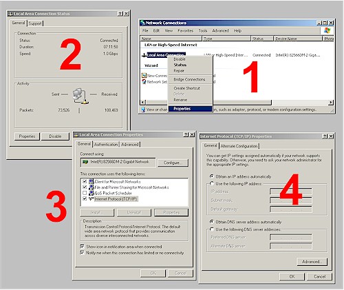
Step 1: Connect a computer that is set to obtain its IP address information automatically to a LAN port on the wireless router that you want to convert to an AP. If you don't know how to do this, Figure 1 shows the applicable Windows XP screens. (Get to the Network Connections window by Start > Settings > Network Connections.)

Checking for "Obtain an IP address automatically"
Click to enlarge image

Figure 1: Checking for "Obtain an IP address automatically"

Log into the admin page of the wireless router that you want to convert to an access point. From here on, I'll call this the "AP".

Step 2: For simple, one segment LANs, there must be only one DHCP server. Your LAN's router has a DHCP server and you don't want the two to conflict. So turn off the DHCP server on the AP. In Figure 2, you can see that the DHCP server in the WRT54G AP has been disabled.

Shut off the DHCP server; change the IP

Figure 2: Shut off the DHCP server; change the IP

Step 3: Find your LAN Router's DHCP server range. Figure 3 shows the Basic Network Settings page of the D-Link DGL-4300 that is my LAN's router. This is where the DHCP server controls happen to be. Different routers might have the DHCP server controls on a separate page, so you may have to poke around a little.

LAN router settings

Figure 3: LAN router settings

The 4300 normally has its Router IP Address set to 192.168.0.1 by default. But you can see in Figure 3, I changed it to 10.168.3.254. This shifted the DHCP server to the 10.168.3.X subnet instead of the 192.168.0.X. I also could have used 10.168.3.1 or any address as long as it wasn't between 10.168.3.100 and 10.168.3.249, which is the DHCP server's range.

The bottom line is that the my LAN router's DHCP server range is 10.168.3.100 to 10.168.3.249.

Step 4: Change the address of the AP to an unused LAN IP address. This will ensure that you can reach the admin pages of the AP to change settings when needed. Referring back to Figure 2, you can see that I set the AP to 10.168.3.250. Again, this could be any IP from 10.168.3.1 to 10.168.3.99 or 10.168.3.250 to 10.168.3.254, which are all outside the LAN DHCP server range.

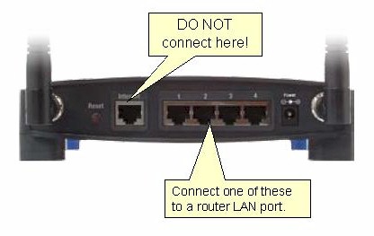
Step 5: Connect the AP to the LAN. Unplug the computer you used to configure the AP and plug it back into one of your LAN router's switch ports. Now take an Ethernet cable, plug one end into another unused router switch port and the other end into one of the AP's LAN ports. Be sure to use a LAN port and not the WAN port. Figure 4 shows the proper connection for the WRT54G.

AP connection detail

Figure 4: AP connection detail

Step 6: Check the AP LAN connection. You should now be able to use any of your LAN's computers to reach the AP. So open a browser, enter the address generic viagra 50mg that you set for the AP in Step 4 (which is at 10.168.3.250 in this example) and you should get the login prompt.

If you don't get the prompt, recheck that you have the Ethernet cable running from LAN port to LAN port on your router's switch and the AP. The respective port lights on the router and AP should be lit.

Step 7: Check the AP wireless connection. Fire up a wireless notebook or other client and check that it properly associates and pulls an IP address from your LAN router's DHCP server. Congratulations! You now have a new AP!

Permalink • Print • Comment

December 19, 2007

Wireless Network

Q:
I just set up a wireless network in my home and while I love it, I'm still a little concerned about others being able to use cialis reviews my signal or even hack into my computer. I was told that hiding my SSID will take care of the problem, but I'm not sold on that idea. I'm not even sure what an SSID is or how to hide it. Can you please help me? Thanks!

A:
First of all, I want to welcome you to the world of wireless! I've been using a wireless connection in my home for a few years now and I absolutely love it. I'm sure you will too! And it's very impressive that you're already concerned about your safety when it comes to using your wireless network. A lot of people don't start worrying about that until it's too late, so it's great that you're already so far ahead of the game. I think your question will help a lot of other readers out there who are using wireless networks as well. I just love that!

As we all know, when you use a wireless router, there's always a chance that other computers will be able to pick up your signal and use it, without you ever knowing a thing about it. Even more than that, there's always the risk of your computer being hacked into as well. So, what can you do to keep yourself safe when using your wireless connection? Well, the person who asked today's question mentioned hiding their SSID and while that helps, it's not always the best solution. Let's take a look at our options!

To begin, wireless routers are set up to send out a beacon called the Service Set IDentifier (SSID), which is what helps your wireless devices (laptop, etc.) connect to the Internet. The main purpose of the SSID is to broadcast wireless signals and invite available devices within range to connect to them. Now, if a device doesn't know a network's SSID, it will not be able to connect. So, if you change your SSID settings, only the people who know the SSID will be able to connect to your wireless network. That can help keep some of the "outsiders" away.

Now, while hiding your SSID keeps casual users at bay, you could still have trouble with hackers. Unfortunately, a hacker who is determined enough to get into your network will find a way. If they have the right kind of software, they will be able to easily gain access to your computer. Plus, changing your SSID can result in a slower performance and it could take you longer to connect to the Internet. Who wants that?! Luckily, there are a few other things you can do to keep your wireless network as secure as possible. Let's check them out!

For starters, you can change your router's login and password to be different from the default settings. If you're still using the login and password that came with your router, anyone could connect to it, change your settings and even lock you out. You should also change your SSID to something a little more unique. Most routers come with a name of "default," which is very easy for hackers to figure out. You should change it to something a little more meaningful to yourself. Lastly, you should turn on your encryption. If you do that, your router will not give access to any wireless devices unless they can provide the password you specify. It will also encrypt any communication between your computer and your router so that no one will be able to see what goes on. Note: If your router supports WPA encryption, you should use that over WEP, which is an older version.

Doing the three things I discussed above are your best bets for secure wireless networking, but if you still want to hide your SSID, you can do so by following the directions in your user manual. Every router is different, so your manual should give you detailed directions on how to get the job done. If that doesn't work, you can always contact your ISP for help as well. Either way, it's very important to keep your wireless network as safe as possible. Hopefully one of the above suggestions is just what you've been looking for. Test them out today!

Permalink • Print • Comment
« Previous PageNext Page »
Made with WordPress and a search engine optimized WordPress theme • Sky Gold skin by Denis de Bernardy